KS3R / R
144.530 MHz (Input) 145.130 MHz (Output) -600 kHz Split - PL Tone: 131.8 Hz
Revised 5/31/12

|
The repeater's duplexer was taken from the original SHARC-1 repeater and mounted horizontally at the top of the rack.
The duplexer is manufactured by Sinclair Radio Laboratories (model Q2330 Res-Lok), and consists of 3 high-pass & 3 low-pass tuned cavity filters.
| 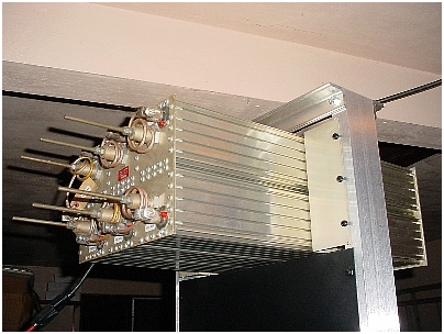
Sinclair Model Q2330 Res-Lok |
|
Also purchased was an in-line coaxial Polyphaser
lightning protection suppressor (Model IS-50NX-C2).
The suppressor is rated for 350W at 125-220 MHz. Insertion loss is equal to or less than 0.1 dB with a VSWR of equal to or less than 1.1:1.
| 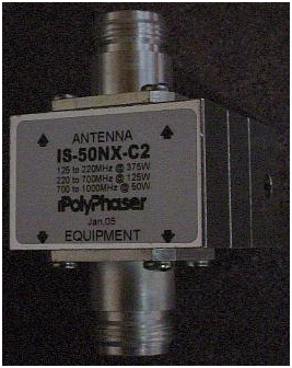
Lightning Protection Suppressor |
|
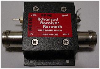
A receiver GaAsFET pre-amp was purchased for the new repeater. The pre-amp is manufactured by Advanced Receiver Research. The model number is P144VDG. The pre-amp
has a 0.5dB noise figure and +25dB of gain. The pre-amp operates on +12VDC. An attenuator will be added on the output of the pre-amp to prevent receiver front-end overload.
| 
|
|
The repeater's power amplifier is manufactured by TE Systems (Model 1406RN). It is a continuous duty, 100W conduction cooled, rack-mounted amplifier. The amplifier assembly
is 8-3/4" high and 4" deep. The amplifier is powered by +13.8VDC.
| 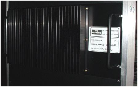
TE Systems Model 1406RN |
|
The amplifier is designed to operate between 144-148 MHz and uses a Motorola MRF-247 Transistor. The test data taken on this unit by the factory indicated that the amplifier produced 105W of RF output with 20W RF input at 147 MHz. DC current was measured to be 12 Amps. The amplifier operates Class C and is FCC Type Accepted (FCC ID: C6V7LR).
| 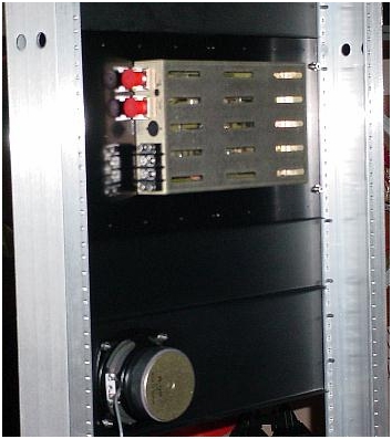
TE Systems Model 1406RN (Receiver Speaker Panel Below) |
|
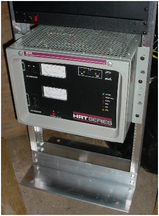
Just above the rectifier supply is a six-outlet AC distribution panel. The distibution panel is used primarily for AC accessories.
The fan for the repeater's driver is located just above the AC distribution panel. The 5" diameter fan pulls air in from the front and blows air through the vertical heatsink fins of the repeater's driver. The fan is powered by +12VDC and is thermally controlled by an Airpax bi-metal thermal switch internally mounted to the repeater driver's PA heatsink. In the event of a fan failure, another bi-metal switch located within the repeater's driver will disable the driver's transmitter.
| 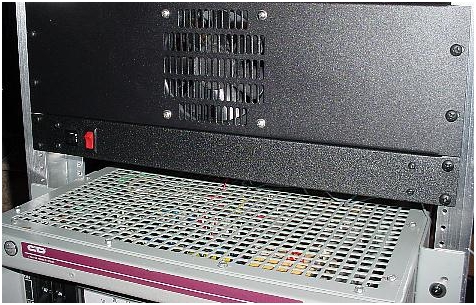
AC Distribution Panel (middle) Rectifier Supply (bottom) |
| The repeater's driver doesn't contain an internal speaker for monitoring receiver audio. Receiver audio is derived from a RCA phono jack on the driver's control panel. The audio from the receiver is wired to a 4-1/2" speaker mounted on a 5-1/4" panel. | 
|
|
The repeater's driver consists of a 100W GE Master Executive II mobile transceiver, converted for repeater operation. The transmitter is turned down to 60W for
continuous duty operation. Installed within the driver is a Micro Computer Concepts (MCC) RC-1000V repeater controller. Also installed within the driver is a CTCSS (PL) encoder & decoder, model TS-64DS, manufactured by Communications Specialist. The output of the driver is connected to a 6dB, 250W power attenuator that reduces the driver output power level to a suitable input level for the external 100W power amplifier. | 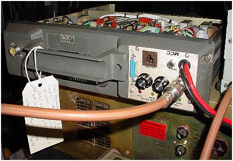
|
| The repeater's driver is mounted vertically in the rack. Andrews 1/2" Superflex cable is used to connect the repeater's receiver and transmitter ports to the duplexer. | 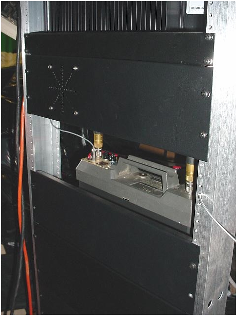
|


